Wiring
IronSight Analog Camera – Wiring & Pinout
This document describes the electrical connections for the Ewing Aerospace IronSight Analog Camera. Proper wiring is required for correct operation, video output, and OSD menu access.
Pinout Overview
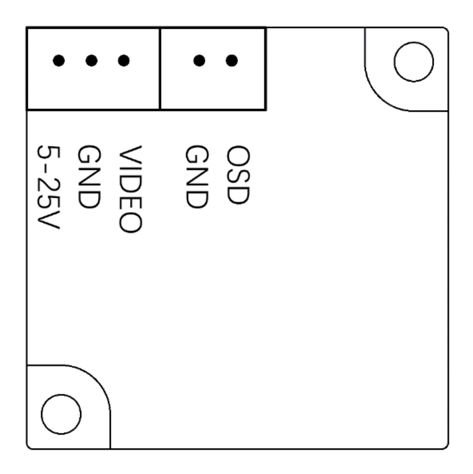
The IronSight camera provides two connectors:
- Main Camera Connector (Power + Video)
- OSD Control Connector (Menu control)
Main Camera Connector (Power & Video)
| Pin | Signal | Description |
|---|---|---|
| 1 | 5–25V | Power input (DC 5 V to 25 V) |
| 2 | GND | Ground |
| 3 | VIDEO | Composite video output (CVBS) |
Notes
- The camera supports a wide input voltage range and may be powered directly from regulated or unregulated system rails within specification.
- Use a clean power source to minimize video noise.
- The VIDEO signal should be routed directly to an analog VTX (such as EwingVTX) or DVR input.
OSD Control Connector
| Pin | Signal | Description |
|---|---|---|
| 1 | GND | Ground |
| 2 | OSD | OSD menu control signal |
Notes
- The OSD pin connects to the included button-based OSD control board.
- This interface allows access to camera configuration menus such as WDR, DNR, aspect ratio, and day/night modes.
- The OSD control board is not required for normal operation once settings are configured.
Typical Wiring Example
| Camera Signal | Connects To |
|---|---|
| 5–25V | System power rail |
| GND | Common ground |
| VIDEO | VTX video input |
| OSD | OSD control board |
Integration Notes
- Always connect ground first, then power.
- Do not hot-plug the camera while powered at high voltage.
- Ensure the VTX and camera share a common ground reference.
- Secure wiring to prevent vibration-induced failures in flight applications.
Safety Notice
Improper wiring or exceeding voltage limits may result in permanent damage to the camera or connected equipment. Verify polarity and voltage before applying power.
© Ewing Aerospace. All rights reserved.